The Kendryte K210 chipset of Sipeed MAix GO (see previous post) has an audio processing unit (APU) which allows beam forming of incoming audio. As accessory of Sipeed MAix GO there is an 6+1 circular microphone array (specs, buy). This post describes how to use the APU of K210 with this array.
Either use arduino ide and add Maixduino(k210) with Boards Manager. (First edit Preferences/Additional Boards (comma separated): http://dl.sipeed.com/MAIX/Maixduino/package_Maixduino_k210_index.json). The code files shown below are then “tabs” inside sketch yourname, e.g. apu6. (main.c becomes the content of the first tab, automatically named yourname).
Or create a new project folder in kendryte standalone sdk (details). Save the code files shown below in this folder. This code is based on the apu example of kendryte standalone sdk. Main reference are the code files of standalone sdk, mainly i2s.h, i2s.c, sysctl.h, sysctl.c, apu.h, apu.c. The code to use the led ring coming with the microphone array is based on this code of GitJer. The schematics have been used, to look up how the MAix GO board (schematic, assembly) and the microphone array (schematic, assembly) are connected.
Source code included on bottom of page.
Current status: Useful for testing is one fixed direction (main.c, currently commented out). Direction detecting code is active (yellow led indicates detected direction, brightness shows amplitude) – including signal of neighbour channels as @MyAmigo suggests in kendryte forum. Detected direction is only used if same direction is detected three times in sequence. Voice output (apu_voc) and detection of direction run at the same time. Currently input sample rate is 44kHz with 24bit data width, and output rate is 22kHz with 24 sysclk cycles but 16bit data width. The corresponding i2s clock rates are shown as console output.
Output is sent to both speakers. To avoid feedback loops the builtin speaker has to be detached (e.g. use a miniature sliding switch) and the other output channel has to be attached to a headphone. Note: the speaker outputs do not have a common ground line and should not be connected (audio amp specs). (In my test setup I had an oscilloscope attached to the input pins of this audio amp to be able to watch the output of the DAC chip.)
Observations: To get reliable i2s sample rates the i2s clocks had to be set by defining the pll2 thresholds (init.c). The function i2s_set_sample_rate is not usable because of rounding errors. To make APU voice output work it seems to be necessary to downsample this output at least by factor 2. I2S controller 0 is linked with the APU and if the clock of I2S0 is set high enough to get 8 input channels with 88kHz only 16 bit data width works. Using 24 (or 32) bit at 88kHz increases the clock even more and this induces a noise with high frequency (see comments in init.c).
Beam forming: There are indications that it works, however it has not yet been tested in a setup without strong reflections. Direction detection with 440 Hz sine wave signal works; led on led ring indicates direction (if currently commented out direction code in main.c is used). The function apu_set_delay() in apu.c suggests that the direction detection and beam forming logic is based on time of flight based superposition of accordingly delayed microphone signals, delay and sum beamformer “DAS BF” (compare chapters 2.1.3, 4.1, 4.2 here, document found by @MyAmigo in kendryte forum)
// file apu6.ino in arduino ide, file main.c in standalone sdk
// use K210 apu to read from 6+1 mic array, auto detect direction, send sound to speaker
// https://blog.spblinux.de/2019/07/sipeed-maix-go-k210-beam-forming/

// switching from kendryte standalone sdk to arduino ide (which is based on this sdk):
// Using arduino ide:
// - stdout not defined by default, thus replace printf and printk by pprintf (defined below)
// - arduino works with c++ compiler, sdk works with c compiler
//   - ino-files (shown without extension in arduino ide) are handled as c++ files
//   - additional files (=tabs in arduino ide) are handled as c files (*.h, *.c) or c++ (*.hpp, *.cpp)
//   - extern "C"{...}; allows to include c files from c++ files
#ifdef __cplusplus
extern "C"{
#endif
#include "init.h"
// only required for standalone sdk
#include <stdio.h>
#include <stdint.h>
#include <stdlib.h>
#include <printf.h>
// end only ...
#include <apu.h>
#include "apu2.h"
#include "mic_array_leds.h"
#ifdef __cplusplus
};
#endif

#ifdef ARDUINO
// in case of standalone sdk pprintf is defined as macro in apu2.h: #define pprintf(...) printf(__VA_ARGS__)
void pprintf(char *fmt, ... ){
        char buf[128]; // resulting string limited to 128 chars
        va_list args;
        va_start (args, fmt );
        vsnprintf(buf, 128, fmt, args);
        va_end (args);
        Serial.print(buf);
}
#endif

int count;
int assert_state;
int32_t dir_max_prev = 0;
uint16_t contex_prev = APU_DIR_CHANNEL_MAX;
uint16_t contex_prev_prev = APU_DIR_CHANNEL_MAX;

int dir_logic(void)
{
  int32_t dir_sum_array[APU_DIR_CHANNEL_MAX];
  int32_t dir_sum = 0;
  int32_t dir_sum_all = 0;
  int32_t dir_max = 0;
  uint16_t contex = 0;

  for (size_t ch = 0; ch < APU_DIR_CHANNEL_MAX; ch++) { //
      dir_sum = 0;
      for (size_t i = 0; i < APU_DIR_CHANNEL_SIZE; i++) {
         dir_sum += (int32_t)APU_DIR_BUFFER[ch][i] * (int32_t)APU_DIR_BUFFER[ch][i];
      }
      dir_sum_array[ch] = dir_sum / APU_DIR_CHANNEL_SIZE; // averaged square sum of one dir channel
  }
  for (size_t ch = 0; ch < APU_DIR_CHANNEL_MAX; ch++) { // dir_sum_all: dir_sum + 50% of dir_sum of both adjacent neighbours
    dir_sum_all = dir_sum_array[ch]
       + (dir_sum_array[(ch+1) % APU_DIR_CHANNEL_MAX]+dir_sum_array[(ch+APU_DIR_CHANNEL_MAX-1) % APU_DIR_CHANNEL_MAX])/2;
    if(dir_sum_all > dir_max){
        dir_max = dir_sum_all;
        contex = ch;
    }
//      pprintf("%d  ", dir_sum);
  }
//    pprintf("   %d\n", contex);
//    pprintf("\n");

  if(contex == contex_prev && contex_prev == contex_prev_prev) { // only use dir channel "contex" if three consecutive times unchanged
    for (int l=0; l<12; l++) {
        if(l==(int)((12*contex)/16.))
        set_light(l, dir_max/APU_DIR_CHANNEL_SIZE, dir_max/APU_DIR_CHANNEL_SIZE, 0);
  //        set_light(l, 0, 0, 1);
        else
        set_light(l, 0, 0, 1);
    }
    write_pixels();
#ifdef ARDUINO
    apu_voc_set_direction((en_bf_dir)contex); // use direction deteced by APU_DIR
#endif
#ifndef ARDUINO
    apu_voc_set_direction(contex); // use direction deteced by APU_DIR
#endif
  }
//  apu_voc_set_direction(6); // use fixed direction for testing
//  set_light((int)((12*6)/16.), 32, 32, 0);
//  write_pixels();


  apu_dir_enable(); // if commented out: direction gets determined (APU_DIR) and set (APU_VOC) only once
  dir_max_prev = dir_max;
  contex_prev_prev = contex_prev;
  contex_prev = contex;
  return 0;
}

int voc_logic(void)
{
  return 0;
}

void setup(void)
{
   // Start the UART
#ifdef ARDUINO
   Serial.begin(115200) ;
   delay(100);
#endif
    //apu_print_setting2();
  uint32_t real_freq, real_freq_source;
  real_freq = sysctl_cpu_get_freq();
  sysctl_pll_set_freq(SYSCTL_PLL0, 320000000UL);
  sysctl_pll_set_freq(SYSCTL_PLL1, 160000000UL);
  uarths_init();
  pprintf("CPU real freq: %u\n", real_freq);
//  real_freq = sysctl_pll_set_freq(SYSCTL_PLL2, 34000000UL); // 44.17kHz sampl., 4 chann. 16bit and threshold 5 (or 1 chan, thresh 47, 22.14kHz)
  real_freq = sysctl_pll_set_freq(SYSCTL_PLL2, 50375000UL); // 43.73kHz sampl., 4 chann. 24bit and threshold 5 (or 1 chan, thresh 47, 21.86kHz)
//  real_freq = sysctl_pll_set_freq(SYSCTL_PLL2, 68000000UL); // 88.54kHz sampl., 4 chann. 16bit and threshold 5 (or 1 chan, thresh 47, 44.27kHz)
  real_freq_source = sysctl_clock_get_freq(SYSCTL_CLOCK_PLL2);
  pprintf("PLL2 real freq: %u (source %u)\n", real_freq, real_freq_source);
  pprintf("git id: %u\n", sysctl->git_id.git_id);
  pprintf("init start.\n");
  clear_csr(mie, MIP_MEIP);
  init_all();
  pprintf("init done.\n");
  set_csr(mie, MIP_MEIP);
  set_csr(mstatus, MSTATUS_MIE);
}

void loop() {
  // put your main code here, to run repeatedly:
  while (1) {
    if (dir_logic_count > 0) {
      dir_logic();
      while (--dir_logic_count != 0) {
        pprintf("d");
//        pprintf("[warning]: %s, restart before prev callback has end\n",
//               "dir_logic");
      }
    }
    if (voc_logic_count > 0) {
      voc_logic();
      while (--voc_logic_count != 0) {
        pprintf("v");
//        pprintf("[warning]: %s, restart before prev callback has end\n",
//               "voc_logic");
      }
    }

  }
}

#ifndef ARDUINO
int main(void)
{
  setup();
  loop();
}
#endif
// file init.c
#include "init.h"
#include <stddef.h>
#include <stdio.h>
#include "gpio.h"
#include "apu.h"
#include "apu2.h"
#include "mic_array_leds.h"
//#define APU_DMA_ENABLE 1
uint64_t dir_logic_count;
uint64_t voc_logic_count;
#if APU_FFT_ENABLE
uint32_t APU_DIR_FFT_BUFFER[APU_DIR_CHANNEL_MAX]
[APU_DIR_CHANNEL_SIZE]
__attribute__((aligned(128)));
uint32_t APU_VOC_FFT_BUFFER[APU_VOC_CHANNEL_SIZE]
__attribute__((aligned(128)));
#else
int16_t APU_DIR_BUFFER[APU_DIR_CHANNEL_MAX][APU_DIR_CHANNEL_SIZE]
__attribute__((aligned(128)));
int16_t APU_VOC_BUFFER[APU_VOC_CHANNEL_SIZE]
__attribute__((aligned(128)));
#endif
int int_apu(void *ctx)
{
apu_int_stat_t rdy_reg = apu->bf_int_stat_reg;
if (rdy_reg.dir_search_data_rdy) {
apu_dir_clear_int_state();
#if APU_FFT_ENABLE
static int ch;
ch = (ch + 1) % 16;
for (uint32_t i = 0; i < 512; i++) { //
uint32_t data = apu->sobuf_dma_rdata;
APU_DIR_FFT_BUFFER[ch][i] = data;
}
if (ch == 0) { //
dir_logic_count++;
}
#else
for (uint32_t ch = 0; ch < APU_DIR_CHANNEL_MAX; ch++) {
for (uint32_t i = 0; i < 256; i++) { //
uint32_t data = apu->sobuf_dma_rdata;
APU_DIR_BUFFER[ch][i * 2 + 0] =
data & 0xffff;
APU_DIR_BUFFER[ch][i * 2 + 1] =
(data >> 16) & 0xffff;
}
}
dir_logic_count++;
#endif
} else if (rdy_reg.voc_buf_data_rdy) {
apu_voc_clear_int_state();
#if APU_FFT_ENABLE
for (uint32_t i = 0; i < 512; i++) { //
uint32_t data = apu->vobuf_dma_rdata;
APU_VOC_FFT_BUFFER[i] = data;
}
#else
/*
for (uint32_t i = 0; i < 256; i++) { //
uint32_t data = apu->vobuf_dma_rdata;
APU_VOC_BUFFER[i * 2 + 0] = data & 0xffff; // right
APU_VOC_BUFFER[i * 2 + 1] = (data >> 16) & 0xffff; // left
}
*/
#if APU_DMA_ENABLE
#else
// use dma to fetch voc data from apu hardware and write it into buffer
/*int16_t buf_zero[]={ // used to verify sample rate: last 56 of 256 samples set to zero
0,0,0,0,0,0,0,0,0,0,
0,0,0,0,0,0,0,0,0,0,
0,0,0,0,0,0,0,0,0,0,
0,0,0,0,0,0,0,0,0,0,
0,0,0,0,0,0,0,0,0,0,
0,0,0,0,0,0,0,0,0,0,
};*/
i2s_data_t data = (i2s_data_t) {
.rx_channel = APU_VOC_DMA_CHANNEL,
.rx_buf = (uint32_t *)APU_VOC_BUFFER,
.rx_len = 256,
.transfer_mode = I2S_RECEIVE
};
// i2s_handle_data_dma(I2S_DEVICE_APU_VOC, data, NULL); // not defined for APU_VOC, so copy code from sdk lib/drivers/i2s.c
// dmac_wait_idle(data.rx_channel); // gets called inside dmac_set_single mode after channel reset (lib/drivers/dmac.c)
sysctl_dma_select((sysctl_dma_channel_t)data.rx_channel, SYSCTL_DMA_SELECT_I2S0_BF_VOICE_REQ);
dmac_set_single_mode(data.rx_channel, (void *)(&apu->vobuf_dma_rdata), data.rx_buf, DMAC_ADDR_NOCHANGE, DMAC_ADDR_INCREMENT,
DMAC_MSIZE_1, DMAC_TRANS_WIDTH_32, data.rx_len);
dmac_wait_done(data.rx_channel);
// use dma to write buffer data to i2s output channel
i2s_set_dma_divide_16(I2S_DEVICE_2, 1);
i2s_send_data_dma(I2S_DEVICE_2, APU_VOC_BUFFER, 256, DMAC_CHANNEL0);
//i2s_send_data_dma(I2S_DEVICE_2, APU_VOC_BUFFER, 200, DMAC_CHANNEL0); // used to verify sample rate
//i2s_send_data_dma(I2S_DEVICE_2, buf_zero, 56, DMAC_CHANNEL0); // used to verify sample rate
#endif
#endif
voc_logic_count++;
} else { //
pprintf("[waring]: unknown %s interrupt cause.\n", __func__);
}
return 0;
}
#if APU_DMA_ENABLE
static void dmac_chanel_interrupt_clear(dmac_channel_number_t channel_num)
{
writeq(0xffffffff, &dmac->channel[channel_num].intclear);
}
int int_apu_dir_dma(void *ctx)
{
uint64_t chx_intstatus =
dmac->channel[APU_DIR_DMA_CHANNEL].intstatus;
if (chx_intstatus & 0x02) {
dmac_chanel_interrupt_clear(APU_DIR_DMA_CHANNEL);
#if APU_FFT_ENABLE
static int ch;
ch = (ch + 1) % 16;
dmac->channel[APU_DIR_DMA_CHANNEL].dar =
(uint64_t)APU_DIR_FFT_BUFFER[ch];
#else
dmac->channel[APU_DIR_DMA_CHANNEL].dar =
(uint64_t)APU_DIR_BUFFER;
#endif
dmac->chen = 0x0101 << APU_DIR_DMA_CHANNEL;
#if APU_FFT_ENABLE
if (ch == 0) { //
dir_logic_count++;
}
#else
dir_logic_count++;
#endif
} else {
pprintf("[warning] unknown dma interrupt. %lx %lx\n",
dmac->intstatus, dmac->com_intstatus);
pprintf("dir intstatus: %lx\n", chx_intstatus);
dmac_chanel_interrupt_clear(APU_DIR_DMA_CHANNEL);
}
return 0;
}
int int_apu_voc_dma(void *ctx)
{
uint64_t chx_intstatus =
dmac->channel[APU_VOC_DMA_CHANNEL].intstatus;
if (chx_intstatus & 0x02) {
dmac_chanel_interrupt_clear(APU_VOC_DMA_CHANNEL);
#if APU_FFT_ENABLE
dmac->channel[APU_VOC_DMA_CHANNEL].dar =
(uint64_t)APU_VOC_FFT_BUFFER;
#else
dmac->channel[APU_VOC_DMA_CHANNEL].dar =
(uint64_t)APU_VOC_BUFFER;
#endif
dmac->chen = 0x0101 << APU_VOC_DMA_CHANNEL;
voc_logic_count++;
} else {
pprintf("[warning] unknown dma interrupt. %lx %lx\n",
dmac->intstatus, dmac->com_intstatus);
pprintf("voc intstatus: %lx\n", chx_intstatus);
dmac_chanel_interrupt_clear(APU_VOC_DMA_CHANNEL);
}
return 0;
}
#endif
void init_fpioa(void)
{
pprintf("init fpioa.\n");
fpioa_init();
// mic
// fpioa_set_function(47, FUNC_GPIOHS4);
fpioa_set_function(23, FUNC_I2S0_IN_D0);
fpioa_set_function(22, FUNC_I2S0_IN_D1);
fpioa_set_function(21, FUNC_I2S0_IN_D2);
fpioa_set_function(20, FUNC_I2S0_IN_D3);
fpioa_set_function(19, FUNC_I2S0_WS);
fpioa_set_function(18, FUNC_I2S0_SCLK);
// dac
fpioa_set_function(34, FUNC_I2S2_OUT_D1);
fpioa_set_function(35, FUNC_I2S2_SCLK);
fpioa_set_function(33, FUNC_I2S2_WS);
}
// copied from lib/drivers/i2s.c
#include <math.h>
uint32_t i2s_set_sample_rate2(i2s_device_number_t device_num, uint32_t sample_rate)
{
ccr_t u_ccr;
uint32_t pll2_clock = 0;
pll2_clock = sysctl_pll_get_freq(SYSCTL_PLL2);
u_ccr.reg_data = readl(&i2s[device_num]->ccr);
/* 0x0 for 16sclk cycles, 0x1 for 24 sclk cycles 0x2 for 32 sclk */
uint32_t v_clk_word_size = (u_ccr.ccr.clk_word_size + 2) * 8;
uint32_t threshold = round(pll2_clock / (sample_rate * 2.0 * v_clk_word_size * 2.0) - 1.5);
sysctl_clock_set_threshold(SYSCTL_THRESHOLD_I2S0 + device_num, threshold);
return sysctl_clock_get_freq(SYSCTL_CLOCK_I2S0 + device_num);
}
void init_i2s(void)
{
// hardware limitation?
// i2s0 clock frequencies of 8.4MHz (4 stereo channels, sample 44.1kHz, 24bit) seems to induce noise of high frequency
// whereas i2s0 clocked with 5.6MHz (4 steroe channels, sample 44.1kHz, 16bit) does not show this noise
// conclusion:
// either use lower sample rates and get higher microphone sensitivity (using 24bit and apu_set_smpl_shift(n) with n=8,7,6...)
// or use 44.1kHz and accept lower sensitivity (max value of gain is 1.9 apu_set_audio_gain(0x7ff))
// or accept noise ...
// (lower input sample rates probably degrade beamforming because beamforming uses time delays
// and probably apu logic internally uses delays which are multiples of sample ticks: delta t = 1/sample frequency)
//
// do not use i2s_set_sample_rate because of rounding errors!!!
// (which make it impossible to set input and output sample rates precisely (they have to match exactly))
// instead directly set threshold of pll2 for i2s (clock of i2sX is 2*(threshold + 1), as used in lib/drivers/i2s.c)
// to adjust the sample rate in small steps change the base frequency of pll2, e.g. sysctl_pll_set_freq(SYSCTL_PLL2, 67737602UL)
//
// downsampling apu_voc output can be used as lowpass for voice output
// apu_set_down_size(0, 3); // dir, voc: 0: /1, 1: /2, 2: /3, 3: /4 ... 15: /16 (first argument is down sampling of apu_dir)
// (i2s sample rate for output , that is threshold used for i2s output has to be set accordingly)
uint32_t real_clock, real_clock_source, pll2_threshold;
pprintf("init i2s.\n");
/* I2s init */
// SCLK_CYCLES refers to whole device and has to be >= biggest channel resolution (of channels of this device)
i2s_init(I2S_DEVICE_0, I2S_RECEIVER, 0x3); // bits 0x3 set: use interrupts - else
i2s_init(I2S_DEVICE_2, I2S_TRANSMITTER, 0x3); // 0x3
//
// either RESOLUTION 16 and apu sample shift 0, or res 24 and apu sample shift 8 (or 7, 6, 5 ... to increase sensitivity)
// (sys cycles has to be >= resolution)
i2s_rx_channel_config(I2S_DEVICE_0, I2S_CHANNEL_0,
RESOLUTION_24_BIT, SCLK_CYCLES_24,
TRIGGER_LEVEL_4, STANDARD_MODE); // has to be standard mode
i2s_rx_channel_config(I2S_DEVICE_0, I2S_CHANNEL_1,
RESOLUTION_24_BIT, SCLK_CYCLES_24,
TRIGGER_LEVEL_4, STANDARD_MODE);
i2s_rx_channel_config(I2S_DEVICE_0, I2S_CHANNEL_2,
RESOLUTION_24_BIT, SCLK_CYCLES_24,
TRIGGER_LEVEL_4, STANDARD_MODE);
i2s_rx_channel_config(I2S_DEVICE_0, I2S_CHANNEL_3,
RESOLUTION_24_BIT, SCLK_CYCLES_24,
TRIGGER_LEVEL_4, STANDARD_MODE);
// input uses 4 stereo channels, output uses 1 stereo channel, so clock of input must be 4 times higher than output clock
// (apart from rounding errors produced by i2s_set_sample_rate(...) the rate argument has to be multiplied by the number of channels used)
// real_clock = 2*i2s_set_sample_rate(I2S_DEVICE_0, 176400); // seems to produce lots of noise unless SCLK_CYCLES is reduced to 16
sysctl_clock_set_threshold(SYSCTL_THRESHOLD_I2S0 + I2S_DEVICE_0, 5); // pll2 divisor is (threshold + 1)
// sample rate == (pll2_freq/pll2_divisor)/(32*4) in case of 16 sys cycles (for left and right channel; using 4 stereo channels)
real_clock = 2*sysctl_clock_get_freq(SYSCTL_CLOCK_I2S0); //clock serves 2 channels, sys_clock_get_freq gets bit rate per channel not i2s clock
real_clock_source = 2*sysctl_clock_get_freq(SYSCTL_CLOCK_I2S0)*(1+sysctl_clock_get_threshold(SYSCTL_THRESHOLD_I2S0));
pll2_threshold = sysctl_clock_get_threshold(SYSCTL_THRESHOLD_I2S0);
pprintf("I2S DEV 0 real clock freq: %u (source %u, threshold %u, divisor %u)\n", real_clock, real_clock_source, pll2_threshold, 1+pll2_threshold);
i2s_tx_channel_config(I2S_DEVICE_2, I2S_CHANNEL_1,
RESOLUTION_16_BIT, SCLK_CYCLES_24, // 24 or 32 sys cycles works as well, if i2s clock is incremented accordingly
TRIGGER_LEVEL_4,
RIGHT_JUSTIFYING_MODE); // needed, PT8211 dual 16bit dac
// real_clock = 2*i2s_set_sample_rate2(I2S_DEVICE_2, 44000);
// sysctl_clock_set_threshold(SYSCTL_THRESHOLD_I2S0 + I2S_DEVICE_2, 23); // pll2 divisor is 2*(threshold + 1); no downsampling: broken apu_voc output
sysctl_clock_set_threshold(SYSCTL_THRESHOLD_I2S0 + I2S_DEVICE_2, 47); // pll2 divisor is (threshold + 1); downsampling by factor 2
// sysctl_clock_set_threshold(SYSCTL_THRESHOLD_I2S0 + I2S_DEVICE_2, 71); // pll2 divisor is (threshold + 1); downsampling by factor 3
// sysctl_clock_set_threshold(SYSCTL_THRESHOLD_I2S0 + I2S_DEVICE_2, 95); // pll2 divisor is (threshold + 1); downsampling by factor 4
// sample rate == (pll2_freq/pll2_divisor)/32 in case of 16 sys cycles (for left and right channel; using 1 stereo channels)
real_clock = 2*sysctl_clock_get_freq(SYSCTL_CLOCK_I2S2); //clock serves 2 channels, sys_clock_get_freq gets bit rate per channel not i2s clock
real_clock_source = 2*sysctl_clock_get_freq(SYSCTL_CLOCK_I2S2)*(1+sysctl_clock_get_threshold(SYSCTL_THRESHOLD_I2S2));
pll2_threshold = sysctl_clock_get_threshold(SYSCTL_THRESHOLD_I2S2);
pprintf("I2S DEV 2 real clock freq: %u (source %u, threshold %u, divisor %u)\n", real_clock, real_clock_source, pll2_threshold, 1+pll2_threshold);
// power on audio amplifier
fpioa_set_function(32, FUNC_GPIO0);
gpio_init();
gpio_set_drive_mode(0, GPIO_DM_OUTPUT);
gpio_set_pin(0, GPIO_PV_HIGH);
}
void init_bf(void)
{
pprintf("init bf.\n");
uint16_t fir_prev_t[] = {
0x020b, 0x0401, 0xff60, 0xfae2, 0xf860, 0x0022,
0x10e6, 0x22f1, 0x2a98, 0x22f1, 0x10e6, 0x0022,
0xf860, 0xfae2, 0xff60, 0x0401, 0x020b,
};
uint16_t fir_post_t[] = {
0xf649, 0xe59e, 0xd156, 0xc615, 0xd12c, 0xf732,
0x2daf, 0x5e03, 0x7151, 0x5e03, 0x2daf, 0xf732,
0xd12c, 0xc615, 0xd156, 0xe59e, 0xf649,
};
uint16_t fir_one[] = { // 32767
0x7fff, 0, 0, 0, 0, 0, 0, 0, 0, 0, 0, 0, 0, 0, 0, 0, 0, 0, 0,
};
uint16_t fir_neg_one[] = { // -32768
0x8000, 0, 0, 0, 0, 0, 0, 0, 0, 0, 0, 0, 0, 0, 0, 0, 0, 0, 0,
};
uint16_t fir_half[] = { // 16384
0x4000, 0, 0, 0, 0, 0, 0, 0, 0, 0, 0, 0, 0, 0, 0, 0, 0, 0, 0,
};
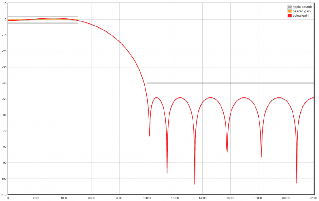
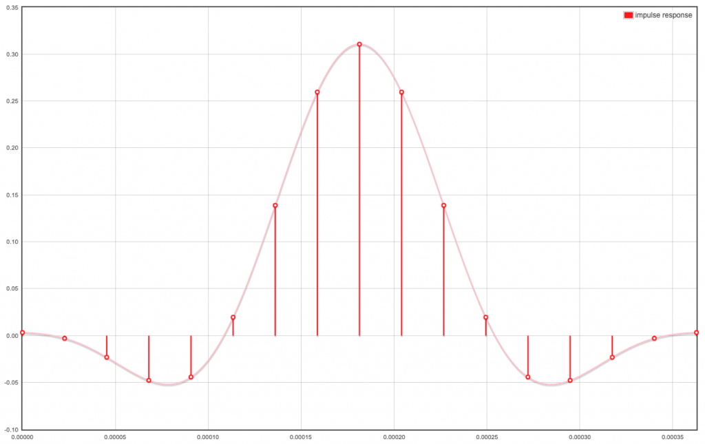
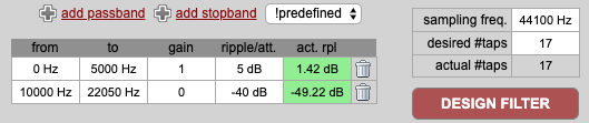
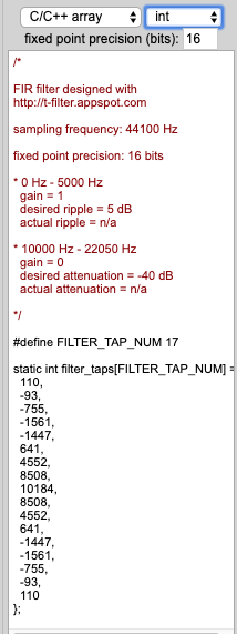
int16_t fir_lowpass_signed[] = { // http://t-filter.engineerjs.com/ 44100 Hz 17 taps pass 0-5000, stop 10000-22050
110,
-93,
-755,
-1561,
-1447,
641,
4552,
8508,
10184,
8508,
4552,
641,
-1447,
-1561,
-755,
-93,
110
};
int16_t fir_lowpass2_signed[] = { // http://t-filter.engineerjs.com/ 44100 Hz 17 taps pass 0-2500, stop 5000-22050
62,
698,
1151,
1911,
2762,
3617,
4351,
4847,
5022,
4847,
4351,
3617,
2762,
1911,
1151,
698,
62
};
int16_t fir_bandpass_signed[] = {
/*
FIR filter designed with
http://t-filter.appspot.com
sampling frequency: 22050 Hz
fixed point precision: 16 bits
* 0 Hz - 12 Hz
gain = 0
desired attenuation = -20 dB
actual attenuation = n/a
* 18 Hz - 1000 Hz
gain = 1
desired ripple = 5 dB
actual ripple = n/a
* 2000 Hz - 11025 Hz
gain = 0
desired attenuation = -20 dB
actual attenuation = n/a
*/
-5173,
-466,
-109,
457,
1170,
1907,
2545,
2979,
3134,
2979,
2545,
1907,
1170,
457,
-109,
-466,
-5173
};
// apu_dir_set_prev_fir(fir_one);
// apu_dir_set_post_fir(fir_one);
// apu_voc_set_prev_fir(fir_neg_one);
// apu_voc_set_post_fir(fir_neg_one);
apu_voc_set_prev_fir((uint16_t *)fir_lowpass2_signed);
apu_voc_set_post_fir((uint16_t *)fir_bandpass_signed);
// apu_voc_set_prev_fir((uint16_t *)fir_prev_t);
// apu_voc_set_post_fir((uint16_t *)fir_post_t);
// apu_voc_set_prev_fir((uint16_t *)fir_one);
// apu_voc_set_post_fir((uint16_t *)fir_one);
apu_dir_set_prev_fir((uint16_t *)fir_lowpass_signed);
apu_dir_set_post_fir((uint16_t *)fir_lowpass_signed);
// lib/drivers/include/apu.h has hardcoded I2S rate of 44100: #define I2S_FS 44100;
// lib/drivers/apu.c: float cm_tick = (float)SOUND_SPEED * 100 / I2S_FS; /*distance per tick (cm)*/
// redefine I2S_FS in apu2.h using #undef I2S_FS and #define I2S_FS 22050
// apu2.h and apu2.c define apu_set_delay2 which allows a center mic on an arbitrary i2s channel (required for maix go)
// apu_set_delay2(4, 6, 0); // radius of mic circle (cm), # mics in circle, no center mic (0/1)
// apu_set_delay2(4, 6, 1); // radius of mic circle (cm), # mics in circle, with center mic (0/1)
apu_set_delay2(4, 6, 7); // radius of mic circle (cm), # mics in circle 0,1...5, with center mic as mic number 7
// apu_set_smpl_shift(APU_SMPL_SHIFT); // 0 corresponds to i2s input 16bit
// apu_set_smpl_shift(8); // corresponds to i2s input 24bit instead of 16 bit: using 7,6... increases sensitivity
apu_set_smpl_shift(6); // corresponds to i2s input 24bit instead of 16 bit: using 7,6... increases sensitivity: useful with bandpass filter
apu_voc_set_saturation_limit(APU_SATURATION_VPOS_DEBUG, // 0x07ff
APU_SATURATION_VNEG_DEBUG); // 0xf800
apu_set_audio_gain(APU_AUDIO_GAIN_TEST); // 1 << 10 == 1.0
// apu_set_audio_gain(0x200); // 0.5
// apu_set_audio_gain(0x100); // 0.25
// apu_set_audio_gain(0x7ff); // 1.9 max gain
// apu_set_channel_enabled(0x3f); // circle mics 0,1...5; no center mic
// apu_set_channel_enabled(0x15); // only circle mics 0,3,5; no center mic
// apu_set_channel_enabled(0x7f);
apu_set_channel_enabled(0xbf); // circle mics 0,1...5; center mic 7: requires apu_set_delay2
// apu_set_down_size(0, 0); // dir, voc: 0: /1, 1: /2, 2: /3 ... 15: /16
apu_set_down_size(0, 1); // downsampling of apu_voc; output i2s rate for apu_voc has to be divided accordingly;
// current status: rather high sensity; no sampling distortions (scope: broken curves with missing pieces); 440hz beamforming seems to work: 100% in preferred direction, 50% about 30 degrees away; 440hz sine is accompagnied by 30hz(??) humming sound, 440hz sine waves are wobbling, like frequency modulated
#if APU_FFT_ENABLE
apu_set_fft_shift_factor(1, 0xaa);
#else
apu_set_fft_shift_factor(0, 0);
#endif
apu_set_interrupt_mask(APU_DMA_ENABLE, APU_DMA_ENABLE);
#if APU_DIR_ENABLE
apu_dir_enable();
#endif
#if APU_VOC_ENABLE
apu_voc_enable(1);
#else
apu_voc_enable(0);
#endif
}
#if APU_DMA_ENABLE
void init_dma(void)
{
pprintf("%s\n", __func__);
// dmac enable dmac and interrupt
// union dmac_cfg_u dmac_cfg;
dmac_cfg_u_t dmac_cfg;
dmac_cfg.data = readq(&dmac->cfg);
dmac_cfg.cfg.dmac_en = 1;
dmac_cfg.cfg.int_en = 1;
writeq(dmac_cfg.data, &dmac->cfg);
sysctl_dma_select(SYSCTL_DMA_CHANNEL_0 + APU_DIR_DMA_CHANNEL,
SYSCTL_DMA_SELECT_I2S0_BF_DIR_REQ);
sysctl_dma_select(SYSCTL_DMA_CHANNEL_0 + APU_VOC_DMA_CHANNEL,
SYSCTL_DMA_SELECT_I2S0_BF_VOICE_REQ);
}
#endif
void init_dma_ch(int ch, volatile uint32_t *src_reg, void *buffer,
size_t size_of_byte)
{
pprintf("%s %d\n", __func__, ch);
dmac->channel[ch].sar = (uint64_t)src_reg;
dmac->channel[ch].dar = (uint64_t)buffer;
dmac->channel[ch].block_ts = (size_of_byte / 4) - 1;
dmac->channel[ch].ctl =
(((uint64_t)1 << 47) | ((uint64_t)15 << 48)
| ((uint64_t)1 << 38) | ((uint64_t)15 << 39)
| ((uint64_t)3 << 18) | ((uint64_t)3 << 14)
| ((uint64_t)2 << 11) | ((uint64_t)2 << 8) | ((uint64_t)0 << 6)
| ((uint64_t)1 << 4) | ((uint64_t)1 << 2) | ((uint64_t)1));
/*
* dmac->channel[ch].ctl = (( wburst_len_en ) |
* ( wburst_len ) |
* ( rburst_len_en ) |
* ( rburst_len ) |
* (one transaction:d) |
* (one transaction:s) |
* ( dst width ) |
* ( src width ) |
* ( dinc,0 inc )|
* ( sinc:1,no inc ));
*/
dmac->channel[ch].cfg = (((uint64_t)1 << 49) | ((uint64_t)ch << 44)
| ((uint64_t)ch << 39) | ((uint64_t)2 << 32));
/*
* dmac->channel[ch].cfg = (( prior ) |
* ( dst_per ) |
* ( src_per ) |
* ( peri to mem ));
* 01: Reload
*/
dmac->channel[ch].intstatus_en = 0x2; // 0xFFFFFFFF;
dmac->channel[ch].intclear = 0xFFFFFFFF;
dmac->chen = 0x0101 << ch;
}
void init_interrupt(void)
{
plic_init();
// bf
plic_set_priority(IRQN_I2S0_INTERRUPT, 4);
plic_irq_enable(IRQN_I2S0_INTERRUPT);
plic_irq_register(IRQN_I2S0_INTERRUPT, int_apu, NULL);
#if APU_DMA_ENABLE
// dma
plic_set_priority(IRQN_DMA0_INTERRUPT + APU_DIR_DMA_CHANNEL, 4);
plic_irq_register(IRQN_DMA0_INTERRUPT + APU_DIR_DMA_CHANNEL,
int_apu_dir_dma, NULL);
plic_irq_enable(IRQN_DMA0_INTERRUPT + APU_DIR_DMA_CHANNEL);
// dma
plic_set_priority(IRQN_DMA0_INTERRUPT + APU_VOC_DMA_CHANNEL, 4);
plic_irq_register(IRQN_DMA0_INTERRUPT + APU_VOC_DMA_CHANNEL,
int_apu_voc_dma, NULL);
plic_irq_enable(IRQN_DMA0_INTERRUPT + APU_VOC_DMA_CHANNEL);
#endif
}
/*
void init_ws2812b(void)
{
gpiohs->output_en.bits.b4 = 1;
gpiohs->output_val.bits.b4 = 0;
}
*/
void init_all(void)
{
init_fpioa();
// init_pll();
init_interrupt();
init_i2s();
init_bf();
if (APU_DMA_ENABLE) {
#if APU_DMA_ENABLE
init_dma();
#endif
#if APU_FFT_ENABLE
init_dma_ch(APU_DIR_DMA_CHANNEL,
&apu->sobuf_dma_rdata,
APU_DIR_FFT_BUFFER[0], 512 * 4);
init_dma_ch(APU_VOC_DMA_CHANNEL,
&apu->vobuf_dma_rdata, APU_VOC_FFT_BUFFER,
512 * 4);
#else
init_dma_ch(APU_DIR_DMA_CHANNEL,
&apu->sobuf_dma_rdata, APU_DIR_BUFFER,
512 * 16 * 2);
init_dma_ch(APU_VOC_DMA_CHANNEL,
&apu->vobuf_dma_rdata, APU_VOC_BUFFER,
512 * 2);
#endif
}
// init_ws2812b();
init_mic_array_lights();
for (int l=0; l<12; l++) set_light(l, 0, 0, 0);
write_pixels();
// apu_print_setting();
}
// file init.h
#pragma once
#include <stdint.h>
#include <plic.h>
#include <i2s.h>
#include <sysctl.h>
#include <dmac.h>
#include <fpioa.h>
#include "uarths.h"
#include "gpiohs.h"


#ifndef APU_DIR_ENABLE
#define APU_DIR_ENABLE 1
#endif

#ifndef APU_VOC_ENABLE
#define APU_VOC_ENABLE 1
#endif

#ifndef APU_DMA_ENABLE
#define APU_DMA_ENABLE 0
#endif

#ifndef APU_FFT_ENABLE
#define APU_FFT_ENABLE 0
#endif

#ifndef APU_DATA_DEBUG
#define APU_DATA_DEBUG 0
#endif

#ifndef APU_GAIN_DEBUG
#define APU_GAIN_DEBUG 0
#endif

#ifndef APU_SETDIR_DEBUG
#define APU_SETDIR_DEBUG 0
#endif

#ifndef APU_SMPL_SHIFT
#define APU_SMPL_SHIFT 0x00
#endif

#ifndef APU_SATURATION_DEBUG
#define APU_SATURATION_DEBUG 0
#endif

#ifndef APU_SATURATION_VPOS_DEBUG
#define APU_SATURATION_VPOS_DEBUG 0x07ff
#endif

#ifndef APU_SATURATION_VNEG_DEBUG
#define APU_SATURATION_VNEG_DEBUG 0xf800
#endif

#ifndef APU_INPUT_CONST_DEBUG
#define APU_INPUT_CONST_DEBUG 0x0
#endif

#ifndef APU_SMPL_SHIFT_DEBUG
#define APU_SMPL_SHIFT_DEBUG 0
#endif

#ifndef I2S_RESOLUTION_TEST
#define I2S_RESOLUTION_TEST RESOLUTION_12_BIT
#endif

#ifndef I2S_SCLK_CYCLES_TEST
#define I2S_SCLK_CYCLES_TEST SCLK_CYCLES_16
#endif

#ifndef SYSCTL_THRESHOLD_I2S0_TEST
#define SYSCTL_THRESHOLD_I2S0_TEST 0xf
#endif

#ifndef APU_AUDIO_GAIN_TEST
#define APU_AUDIO_GAIN_TEST (1 << 10)
#endif

#ifndef APU_PRESETN_DEBUG
#define APU_PRESETN_DEBUG 1
#endif

#ifndef APU_DEBUG_NO_EXIT
#define APU_DEBUG_NO_EXIT 1
#endif


#define APU_DIR_DMA_CHANNEL DMAC_CHANNEL3
#define APU_VOC_DMA_CHANNEL DMAC_CHANNEL4

#define APU_DIR_CHANNEL_MAX 16
#define APU_DIR_CHANNEL_SIZE 512
#define APU_VOC_CHANNEL_SIZE 512

#if APU_FFT_ENABLE
extern uint32_t APU_DIR_FFT_BUFFER[APU_DIR_CHANNEL_MAX]
               [APU_DIR_CHANNEL_SIZE]
  __attribute__((aligned(128)));
extern uint32_t APU_VOC_FFT_BUFFER[APU_VOC_CHANNEL_SIZE]
  __attribute__((aligned(128)));
#else
extern int16_t APU_DIR_BUFFER[APU_DIR_CHANNEL_MAX]
          [APU_DIR_CHANNEL_SIZE]
  __attribute__((aligned(128)));
extern int16_t APU_VOC_BUFFER[APU_VOC_CHANNEL_SIZE]
  __attribute__((aligned(128)));
#endif


extern uint64_t dir_logic_count;
extern uint64_t voc_logic_count;

void init_all(void);
// file mic_arrays_led.c
#include <unistd.h>
#include <stdio.h>
#include "fpioa.h"
#include "sleep.h"
#include "spi.h"

#include "mic_array_leds.h"

// The Sipeed microphone array has 12 SK9822 LEDs
#define NUMPIX 12
uint8_t red[NUMPIX], green[NUMPIX], blue[NUMPIX];
// The SK9822 has an overal brightness factor
uint8_t brightness;

// The buffer to send the data to the mic array
#define TX_LEN 4+NUMPIX*4+4
uint8_t tx_buffer[TX_LEN];

uint8_t busy = 0;
// send the pixel data to the mic array using SPI
void write_pixels()
{
    uint8_t tx_place=0;

    if(busy)
  return;
    busy = 1;
    // the SK9822 first expects 4 times 0000 0000
    for (int i=0; i<4; i++) tx_buffer[tx_place+i] = 0;
    tx_place+=4;

    // write the color data to the tx_buffer
    for (uint8_t i=0; i<NUMPIX; i++) {
        // set the overall brightness factor
        tx_buffer[tx_place] = (0b11100000 | brightness);
        // set the RGB values
        tx_buffer[tx_place+1] = blue[i];
        tx_buffer[tx_place+2] = green[i];
        tx_buffer[tx_place+3] = red[i];
        tx_place += 4;
    }

    // the SK9822 finally expects 4 times 1111 1111
    for (int i=0; i<4; i++) tx_buffer[tx_place+i] = 255;

    // send the data to the mic array
    spi_send_data_standard(0, 0, NULL, 0, tx_buffer, TX_LEN);
    busy = 0;
}


void init_mic_array_lights(void)
{
    // data pin
    fpioa_set_function(24, FUNC_SPI0_D0); //MOSI
    // clock pin
    fpioa_set_function(25, FUNC_SPI0_SCLK); //CLK
    // init SPI
    spi_init(0, SPI_WORK_MODE_0, SPI_FF_STANDARD, 8, 0);
//    spi_set_clk_rate(0, 20000000); // datasheet max 30MHz
    spi_set_clk_rate(0, 500000);

    // set the overall brighness factor
    brightness = 5;
}

void set_light(int light_number, int R, int G, int B)
{
   red[light_number] = R;
   green[light_number] = G;
   blue[light_number] = B;
}
// file mic_arrays_led.h
// send the pixel data to the mic array using SPI
void write_pixels();

void init_mic_array_lights(void);

void set_light(int light_number, int R, int G, int B);
// file apu2.c
/* Copyright 2018 Canaan Inc.
 *
 * Licensed under the Apache License, Version 2.0 (the "License");
 * you may not use this file except in compliance with the License.
 * You may obtain a copy of the License at
 *
 *     http://www.apache.org/licenses/LICENSE-2.0
 *
 * Unless required by applicable law or agreed to in writing, software
 * distributed under the License is distributed on an "AS IS" BASIS,
 * WITHOUT WARRANTIES OR CONDITIONS OF ANY KIND, either express or implied.
 * See the License for the specific language governing permissions and
 * limitations under the License.
 */
#include <math.h>
#include <stddef.h>
#include <stdint.h>
#include <printf.h>
#include "apu.h"
#include "apu2.h"
#include "syscalls.h"
#include "sysctl.h"

#include <apu.h>
#include "apu2.h"


static void print_fir2(const char *member_name, volatile apu_fir_coef_t *pfir)
{
    pprintf("  for(int i = 0; i < 9; i++){\n");
    for(int i = 0; i < 9; i++)
    {
//        apu_fir_coef_t fir = pfir[i];
        apu_fir_coef_t fir;
        fir = pfir[i];

        pprintf("    apu->%s[%d] = (apu_fir_coef_t){\n", member_name, i);
        pprintf("      .fir_tap0 = 0x%x,\n", fir.fir_tap0);
        pprintf("      .fir_tap1 = 0x%x\n", fir.fir_tap1);
        pprintf("    };\n");
    }
    pprintf("  }\n");
}
void apu_print_setting2(void)
{
    pprintf("void apu_setting(void) {\n");
    apu_ch_cfg_t bf_ch_cfg_reg = apu->bf_ch_cfg_reg;

    pprintf("  apu->bf_ch_cfg_reg = (apu_ch_cfg_t){\n");
    pprintf("    .we_audio_gain = 1, .we_bf_target_dir = 1, .we_bf_sound_ch_en = 1,\n");
    pprintf("    .audio_gain = 0x%x, .bf_target_dir = %d, .bf_sound_ch_en = %d, .data_src_mode = %d\n",
           bf_ch_cfg_reg.audio_gain, bf_ch_cfg_reg.bf_target_dir, bf_ch_cfg_reg.bf_sound_ch_en, bf_ch_cfg_reg.data_src_mode);
    pprintf("  };\n");

    apu_ctl_t bf_ctl_reg = apu->bf_ctl_reg;

    pprintf("  apu->bf_ctl_reg = (apu_ctl_t){\n");
    pprintf("    .we_bf_stream_gen = 1, .we_bf_dir_search_en = 1,\n");
    pprintf("    .bf_stream_gen_en = %d, .bf_dir_search_en = %d\n",
           bf_ctl_reg.bf_stream_gen_en, bf_ctl_reg.bf_dir_search_en);
    pprintf("  };\n");

    pprintf("  for(int i = 0; i < 16; i++){\n");
    for(int i = 0; i < 16; i++)
    {
        apu_dir_bidx_t bidx0 = apu->bf_dir_bidx[i][0];
        apu_dir_bidx_t bidx1 = apu->bf_dir_bidx[i][1];

        pprintf("    apu->bf_dir_bidx[%d][0] = (apu_dir_bidx_t){\n", i);
        pprintf("      .dir_rd_idx0 = 0x%x,\n", bidx0.dir_rd_idx0);
        pprintf("      .dir_rd_idx1 = 0x%x,\n", bidx0.dir_rd_idx1);
        pprintf("      .dir_rd_idx2 = 0x%x,\n", bidx0.dir_rd_idx2);
        pprintf("      .dir_rd_idx3 = 0x%x\n", bidx0.dir_rd_idx3);
        pprintf("    };\n");
        pprintf("    apu->bf_dir_bidx[%d][1] = (apu_dir_bidx_t){\n", i);
        pprintf("      .dir_rd_idx0 = 0x%x,\n", bidx1.dir_rd_idx0);
        pprintf("      .dir_rd_idx1 = 0x%x,\n", bidx1.dir_rd_idx1);
        pprintf("      .dir_rd_idx2 = 0x%x,\n", bidx1.dir_rd_idx2);
        pprintf("      .dir_rd_idx3 = 0x%x\n", bidx1.dir_rd_idx3);
        pprintf("    };\n");
    }
    pprintf("  }\n");

    print_fir2("bf_pre_fir0_coef", apu->bf_pre_fir0_coef);
    print_fir2("bf_post_fir0_coef", apu->bf_post_fir0_coef);
    print_fir2("bf_pre_fir1_coef", apu->bf_pre_fir1_coef);
    print_fir2("bf_post_fir1_coef", apu->bf_post_fir1_coef);

    apu_dwsz_cfg_t bf_dwsz_cfg_reg = apu->bf_dwsz_cfg_reg;

    pprintf("  apu->bf_dwsz_cfg_reg = (apu_dwsz_cfg_t){\n");
    pprintf("    .dir_dwn_siz_rate = %d, .voc_dwn_siz_rate = %d\n",
           bf_dwsz_cfg_reg.dir_dwn_siz_rate, bf_dwsz_cfg_reg.voc_dwn_siz_rate);
    pprintf("  };\n");

    apu_fft_cfg_t bf_fft_cfg_reg = apu->bf_fft_cfg_reg;

    pprintf("  apu->bf_fft_cfg_reg = (apu_fft_cfg_t){\n");
    pprintf("    .fft_enable = %d, .fft_shift_factor = 0x%x\n",
           bf_fft_cfg_reg.fft_enable, bf_fft_cfg_reg.fft_shift_factor);
    pprintf("  };\n");

    apu_int_mask_t bf_int_mask_reg = apu->bf_int_mask_reg;

    pprintf("  apu->bf_int_mask_reg = (apu_int_mask_t){\n");
    pprintf("    .dir_data_rdy_msk = %d, .voc_buf_rdy_msk = %d\n",
           bf_int_mask_reg.dir_data_rdy_msk, bf_int_mask_reg.voc_buf_rdy_msk);
    pprintf("  };\n");

    pprintf("}\n");
}
/*
 * radius mic_num_a_circle: the num of mic per circle; center: 0: no center mic, 1:have center mic
 * center==1: center mic is channel after circle mics; (is channel number given by variable mic_num_a_circle)
 * center>1: center mic is channel given by variable center (== channel of last mic used)
 * e.g.: circle 0,1,2...5 and center is 7
 */
void apu_set_delay2(float radius, uint8_t mic_num_a_circle, uint8_t center)
{
    uint8_t offsets[16][8];
    int i, j;
    float seta[8], delay[8], hudu_jiao;
    float cm_tick = (float)SOUND_SPEED * 100 / I2S_FS; /*distance per tick (cm)*/
    float min;

    if(center == 1) // if center>0, then make sure that center variable is set to channel of last mic used
  center = mic_num_a_circle;

    for(i = 0; i < mic_num_a_circle; ++i)
    {
        seta[i] = 360 * i / mic_num_a_circle;
        hudu_jiao = 2 * M_PI * seta[i] / 360;
        delay[i] = radius * (1 - cos(hudu_jiao)) / cm_tick;
    }
    if(center)
//        delay[mic_num_a_circle] = radius / cm_tick;
        delay[center] = radius / cm_tick;

//    for(i = 0; i < mic_num_a_circle + center; ++i)
    for(i = 0; i < (center==0 ? mic_num_a_circle : center+1); ++i)
    {
        offsets[0][i] = (int)(delay[i] + 0.5);
    }
    for(; i < 8; i++)
        offsets[0][i] = 0;

    for(j = 1; j < DIRECTION_RES; ++j)
    {
        for(i = 0; i < mic_num_a_circle; ++i)
        {
            seta[i] -= 360 / DIRECTION_RES;
            hudu_jiao = 2 * M_PI * seta[i] / 360;
            delay[i] = radius * (1 - cos(hudu_jiao)) / cm_tick;
        }
        if(center)
//            delay[mic_num_a_circle] = radius / cm_tick;
            delay[center] = radius / cm_tick;

        min = 2 * radius;
        for(i = 0; i < mic_num_a_circle; ++i)
        {
            if(delay[i] < min)
                min = delay[i];
        }
        if(min)
        {
//            for(i = 0; i < mic_num_a_circle + center; ++i)
            for(i = 0; i < (center==0 ? mic_num_a_circle : center+1); ++i)
            {
                delay[i] = delay[i] - min;
            }
        }

//        for(i = 0; i < mic_num_a_circle + center; ++i)
        for(i = 0; i < (center==0 ? mic_num_a_circle : center+1); ++i)
        {
            offsets[j][i] = (int)(delay[i] + 0.5);
        }
        for(; i < 8; i++)
            offsets[0][i] = 0;
    }
    for(size_t i = 0; i < DIRECTION_RES; i++)
    {
        apu_set_direction_delay(i, offsets[i]);
    }
}
// file apu2.h
#ifdef ARDUINO
void pprintf(char *fmt, ... );
#endif
#ifndef ARDUINO
   #define pprintf(...) printf(__VA_ARGS__)
#endif

void apu_print_setting2(void);

// default: #define I2S_FS 44100
//#undef I2S_FS
//#define I2S_FS 88200

/**
 * @brief       I2S host beam-forming direction sample ibuffer read index configure register
 *
 * @param[in]   radius               radius
 * @param[in]   mic_num_a_circle     the num of mic per circle
 * @param[in]   center               0: no center mic, 1:have center mic (>1 set channel of center mic; default: last channel after circle mics)
 *
 */
void apu_set_delay2(float radius, uint8_t mic_num_a_circle, uint8_t center);
// placeholder
// used to hide code blocks